Gpi Fuel Pump Wiring Diagram
Connect pump to the proper voltage source. Your fuel pump is designed, tested, and approved for use with gasoline blends, diesel fuel blends and kerosene.
Gpi Fuel Pump Wiring Diagram Gallery Wiring Diagram Sample
Attach ground wire (green) using green.

Gpi fuel pump wiring diagram. Turn on the pump by removing the nozzle from the holder and pushing up the switch lever. Connect the power cable to the pump wiring per the wiring diagram located inside the electrical coverplate. Turn the pump on by pulling the switch lever down.
Never leave the pump running without fluid. After dispensing fuel, push the switch lever up to turn the pump off and return the nozzle to its holder. Congratulations on receiving your gpi heavy duty fuel pump.
A wiring diagram is a simplified standard pictorial depiction of an electric circuit. Insert the nozzle into the receiving tank and squeeze the handle to dispense fuel. Is a member of the petroleum… utilitech utility transfer pump [148007] user manual transfer pump item #0955642 utility transfer pump.
February 17, 2018 by headcontrolsystem. A wiring diagram usually offers info about the relative. Using wire nuts, connect the black wire to the black wire and the white (or red) wire to the white (or red) wire in the pump’s.
Insert the nozzle into the receiving tank and squeeze the handle to start fuel flow. Assortment of gpi fuel pump wiring diagram. Gpi transfer pumps offer a variety of.
It shows the way the electrical wires are interconnected and will also show where fixtures and components might be connected to the system. Your fuel pump is designed, tested, and approved for use. Please take all due precautions when handling these flammable liquids.
I was wondering if anyone had any experience with wiring up a gpi 12 volt transfer pump, its model 3025 the 25 gpm pump. Dultmeier sales will be closed thursday, november 25th and friday, november 26th in observance of thanksgiving The bottom of the pump.
Remove electrical coverplate (figure 1). The pump contains an automatic bypass valve to prevent Connection to improper voltage will damage pump.
Position the wires inside the electrical cavity The pump has a duty cycle of 30 minutes on and 30 minutes off. Dry running can damage the pump components.
We have everything to the pump connected correctly we believe but when we connect the other end that has alligator clips to the battery on the pickup it just kicks the pump off whenever we turn it on. Fuel your equipment gpi & gpro. Gpi transfer pumps offer a variety of flow rates from 5 to 20 gpm (gallons per minute).
The common elements in the wiring diagram are ground, power source, wire and connection, output devices, switches, resistors, logic gate, lights, etc. Do not leave the pump on for more than 10 minutes with the nozzle closed. To appropriate wiring diagram on page 4.
A wiring diagram usually provides information regarding the loved one setting as well as arrangement of gadgets. It reveals the elements of the circuit as simplified forms, and the power and signal connections between the devices. Remove electrical coverplate (figure 1).
We are pleased to provide you with a system designed to give you maximum reliability and efficiency. Congratulations on receiving your gpi fuel pump. Replace electrical coverplate with all seven screws and tighten securely.
Please take all due precautions when handling these flammable liquids. Congratulations on receiving your gpi® fuel pump. Gpi (great plains industries) repair parts diagrams from dultmeier sales.
Assortment of gpi fuel pump wiring diagram. Install conduit and cable from switchbox to pump electrical box. A wiring diagram is an easy visual representation from the physical connections and physical layout of an electrical system or circuit.
It shows the parts of the circuit as streamlined shapes, and the power and also signal connections in between the tools. A wiring diagram is a streamlined standard pictorial depiction of an electrical circuit. Fuel your equipment gpi &
We are pleased to provide you with a system designed to give you maximum reliability and efficiency. For this reason it is impossible to provide 1 single diagram that will cover all scenarios, however the below is provided as a high level guide that can be used as a starting point. Ground screw located inside the electrical cavity.
To read a wiring diagram, initially you have to find out what fundamental elements are included in the wiring diagram, and which pictorial symbols are employed to represent them. We are pleased to provide you with a system designed to give you maximum reliability and efficiency. Speeduino can be configured in many ways depending on the engine, sensors, ignition and fuel hardware being used.
When done, release the nozzle handle, turn the pump off, and return the nozzle to its holder. Position wires inside the electrical box. Your fuel pump is designed for use with aviation gasoline (avgas 100ll) and kerosene grade (jet a).
See wiring diagram located inside electrical coverplate. 2 danger caution figure 1 figure 2 2. Also view our online catalog for all our gpi products!
Based on the wiring diagram printed.
Gpi Fuel Transfer Pump Wiring Diagram
GPI M150SAU 12 Volt Fuel Transfer Pump (15 GPM) Henrich Fuel Equipment
Gpi Fuel Transfer Pump Wiring Diagram
Gpi Fuel Pump Wiring Diagram blogmaygomes
Gpi Fuel Pump Wiring Diagram blogmaygomes
Gpi Fuel Pump Wiring Diagram Free Wiring Diagram
Gpi Fuel Pump Wiring Diagram Free Wiring Diagram
Gpi Fuel Pump Wiring Diagram blogmaygomes
Fill Rite Transfer Pump Wiring Diagram
GPI M1115SMU 115 Volt Light Duty Fuel Transfer Pump (12 GPM) Henrich Fuel Equipment
Gpi Fuel Pump Wiring Diagram Free Wiring Diagram
GPI HP100UL DualFlo Hand Pump (50 Gal/100 Strokes) Global Fueling
Gpi Fuel Transfer Pump Wiring Diagram
Gpi Fuel Pump Wiring Diagram blogmaygomes
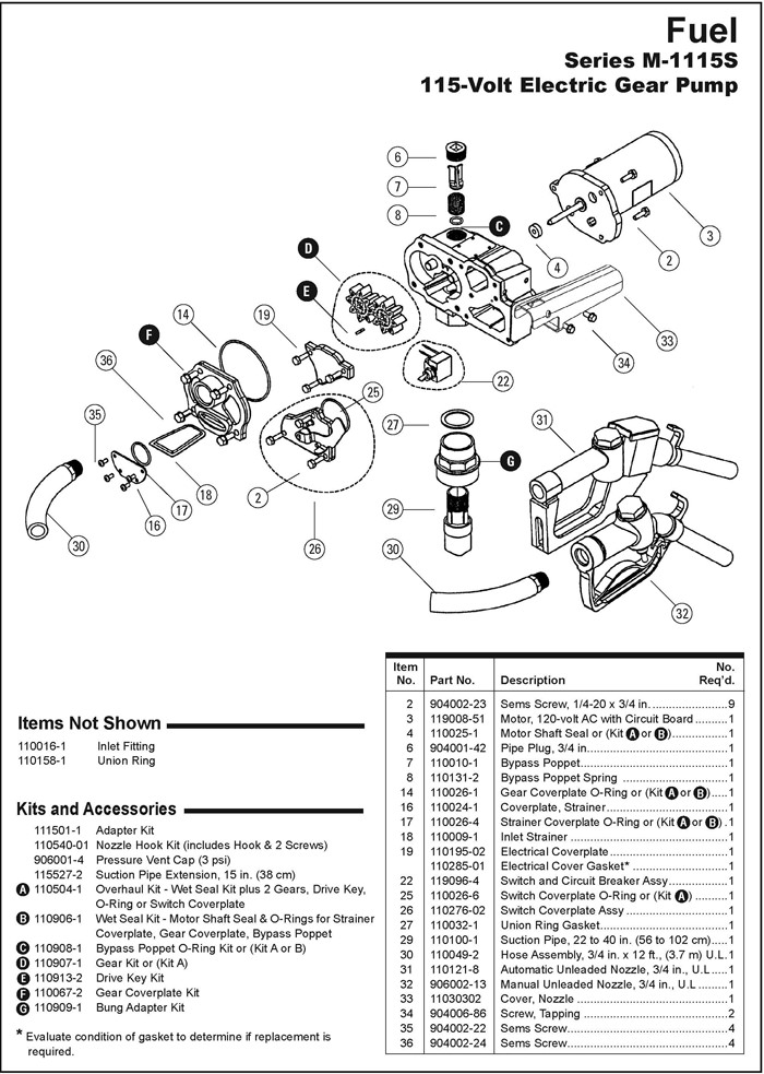
GPI M115S M1115S Parts 115 Volt AC Electric Gear Pump
Gpi Fuel Pump Wiring Diagram Database
Gpi Fuel Pump Wiring Diagram blogmaygomes